|
Fels.fr |
Line Calculation
To set the product and the intensity of the MOBILIS ELITE line, two parameters must be considered simultaneously:
-
The voltage drop on line, which must be below the permissible value
-
The product current capacity, which depends on the ambient temperature and on the duty cycle factor.
The following data must be known:
-
Maximum intensity in continuous operation
-
Type of receivers (cage or slip-ring motors, electronic starters, resistors)
-
Receiver start-up intensity
-
Maximum ambient temperature
-
Maximum distance between a receiver and the nearest feeding point
-
Permissible voltage and voltage drop in continuous operation and at start-up
-
Type of current
-
Running cycle of the receiver (duty cycle).
You can find out immediately the most suitable intensity by connecting to our website www.fels.fr, and using our on-line Mobilis Price Calculator
For help in calculation by our Customer Service Department, Download and fill out the Consultation Sheet
For manual calculation, follow the procedure below:
1.INTENSITY IN CONTINUOUS OPERATION OF THREE PHASE + P.E. LINE FOR OVERHEAD CRANE
Take into account the number of receivers which run simultaneously and calculate the corresponding intensity:
I N = I 1 + I 2 + … + I n
The intensity may be worked out from the power of the receivers. In a three-phase system, this gives:
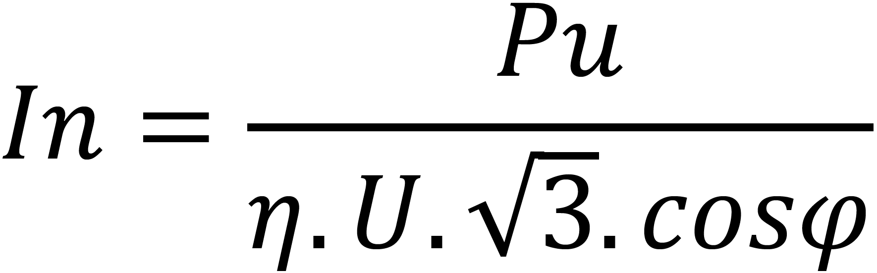 Where:
In : absorbed current (in Amperes)
Pu : power output of the receiver (in Watts)
η : receiver efficiency (between 0.6 and 0.96 for a cage motor)
U : operating voltage (in Volts)
cos ϕ : power factor
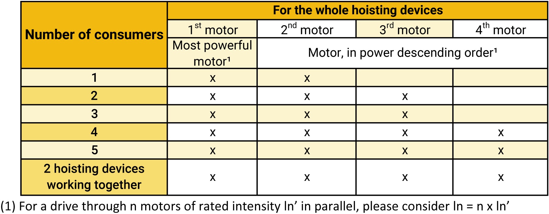
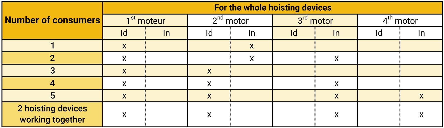
In the absence of information about running simultaneity of consumers, please refer to the table hereunder:
2. CALCULATION OF INTENSITY DURING THE OVERHEAD CRANE MOTOR POWER START-UP PHASE
(2 seconds maximum)
Take into account the number of receivers starting up simultaneously and those already in operation, then calculate the corresponding intensity. When the start-up intensity is not known, find the approximate value as follows:
Id = K . In for a single receiver
Where 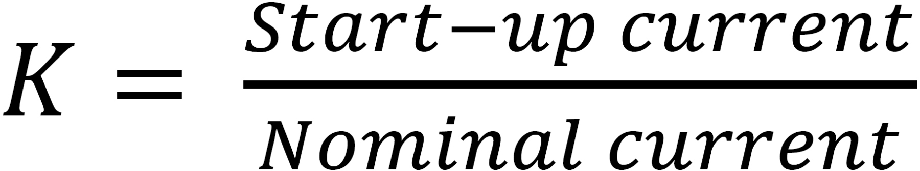
(In general, K = 5 to 6 for cage motors, K = 2 for slipring motors, K = 2 with frequency converter)
In the absence of information about running simultaneity of consumers, please refer to the table hereunder:
3. CALCULATION OF THE VOLTAGE DROP
Under normal running conditions, the voltage drop must be within 2% - 6% of the nominal voltage, according to the operating phase and the upstream/downstream features of the installation. The voltage drop between the origin of installation and any point of use shall not exceed the standard or set values for the applications.
Taking into account the mains voltage, the length of the section considered, the nominal intensity, start-up intensity and the impedance of the conductor selected, voltage drops can be worked out for the start-up phase and normal running phase using the following formulas:
Three-phase alternative current: ΔU = √(3). Z . Lt . I
Continuous current: ΔU = 2 . R . Lt . I
Voltage drop in %: ΔU% = (ΔU/U) x 100
I: current in continuous operation or at start-up, as appropriate (in Amperes)
Lt: length of the section considered (in m), taking Lt as per paragraph 4
Z: line impedance (in Ω/m) (see general technical data, paragraph 12 for Elite, 10 for Movit)
R: line resistance (in Ω/m) (see general technical data, paragraph 12 for Elite, 10 for Movit)
U: mains voltage (in Volts)
In the case of impulse running, the voltage drop can be quickly checked using the "continuous operation" and "start-up" graphs (see below).
When operating at 60Hz, overheating is similar, but voltage drop is greater:
For any given intensity:
X60 being the reactance at 60Hz ⌉ calculate 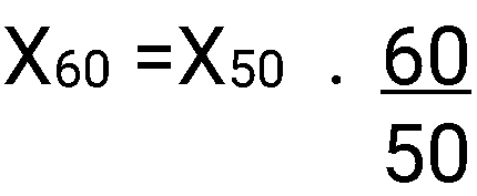
X50 being the reactance at 50Hz ⌋
then re-calculate impedance at 60Hz : 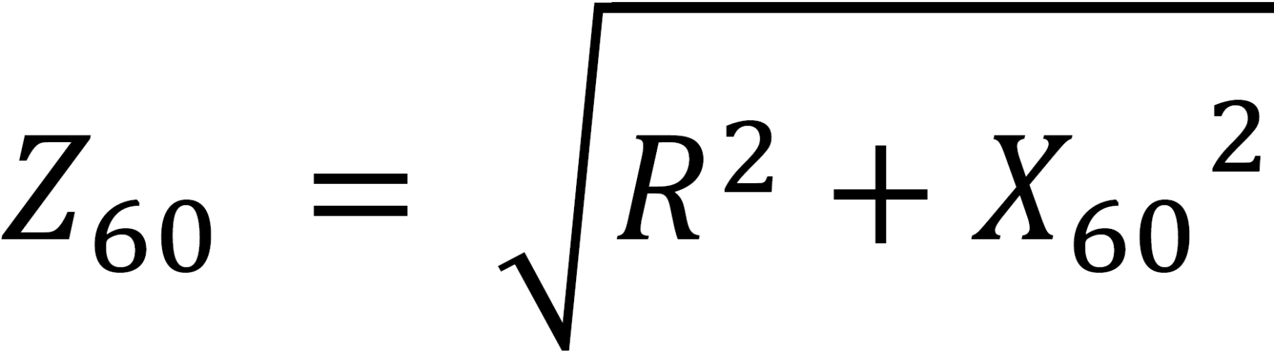
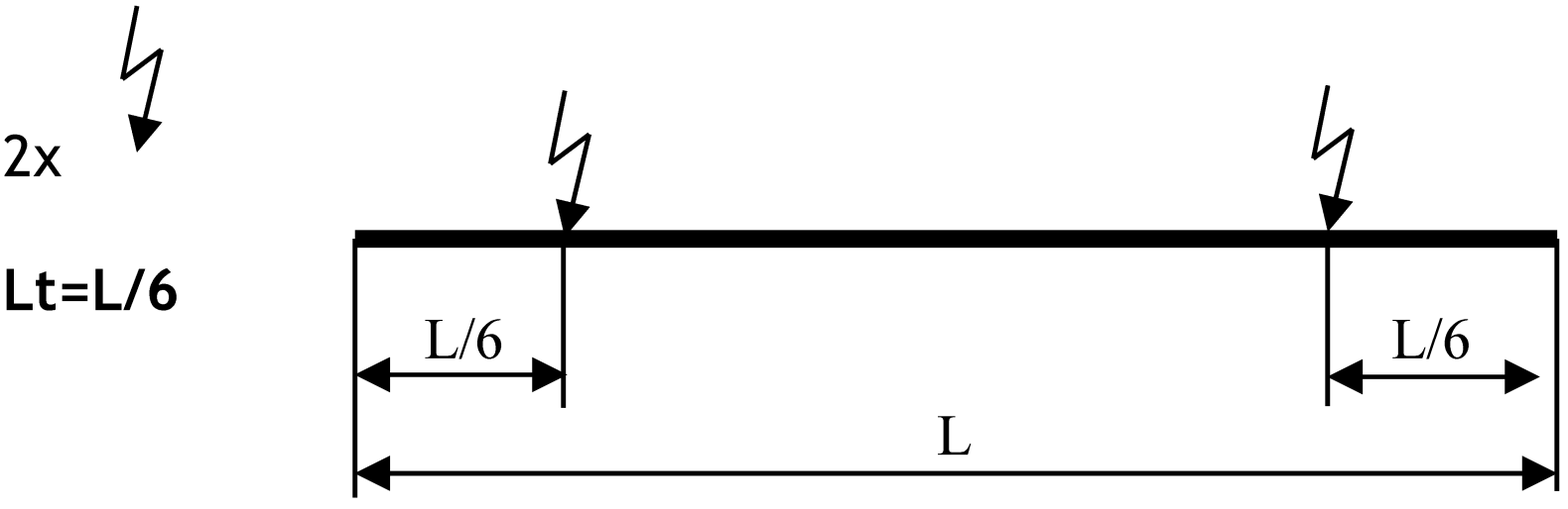
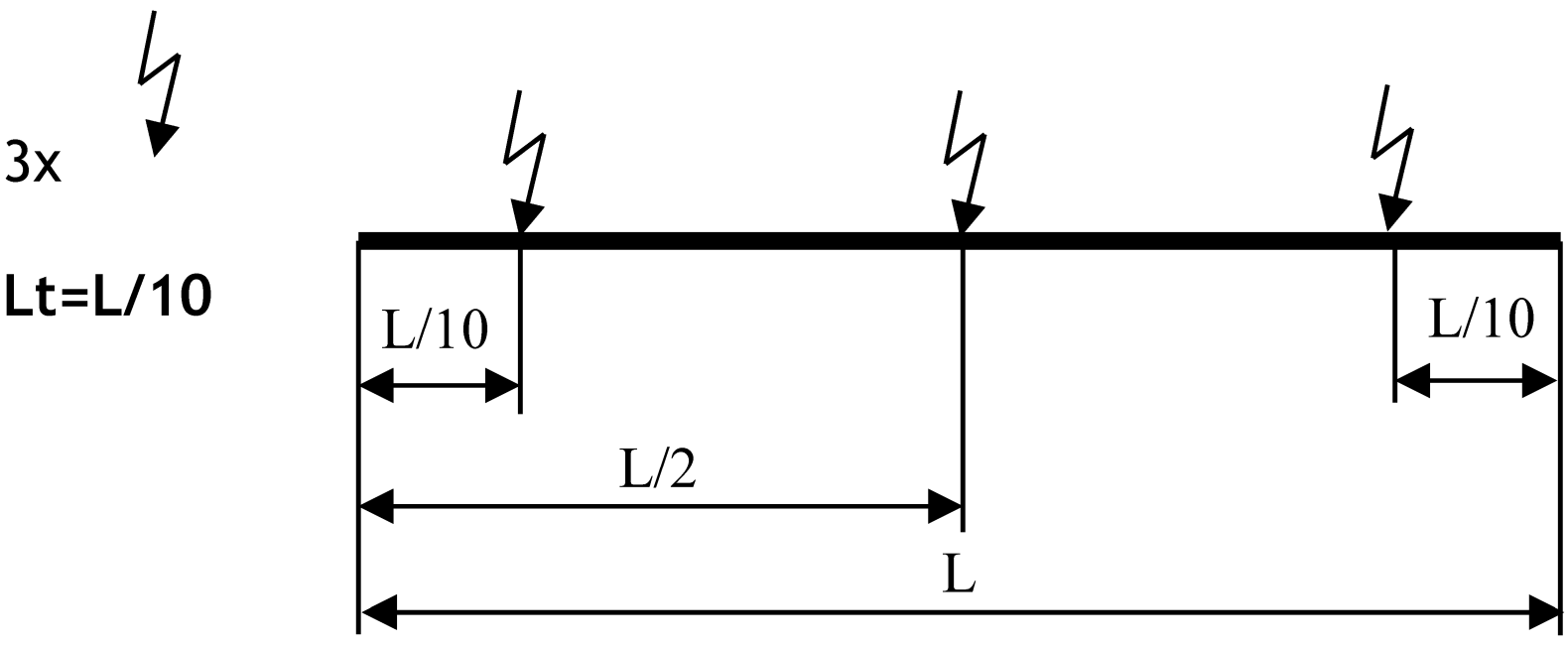
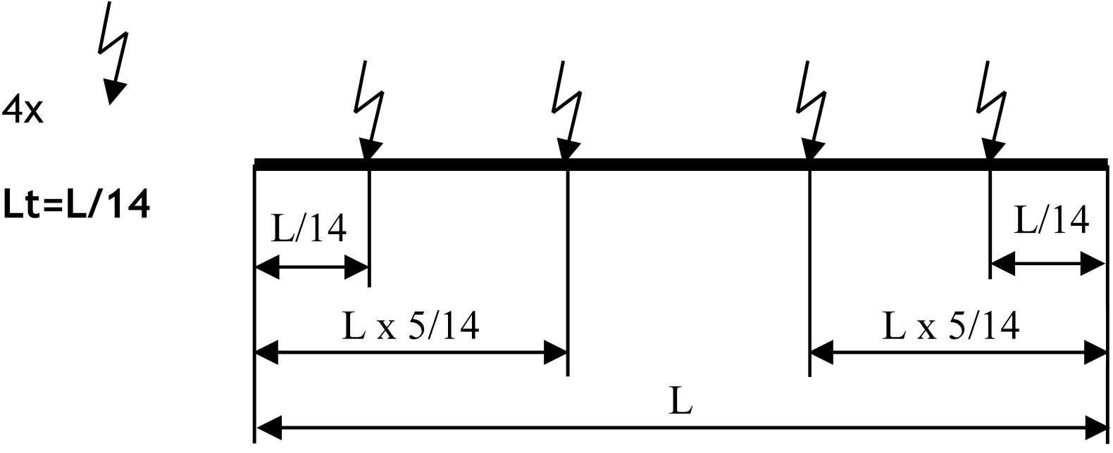
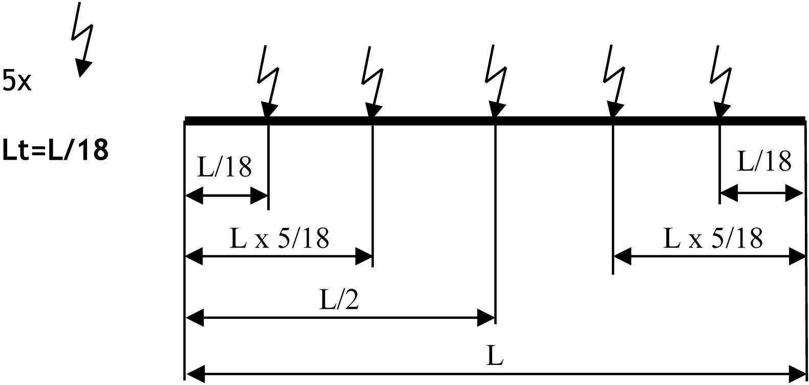
4. FEEDING: LENGTH OF LINE SECTIONS
It is possible to have several feeding points along a line.
The judicious positioning of these points means voltage drop can be reduced.
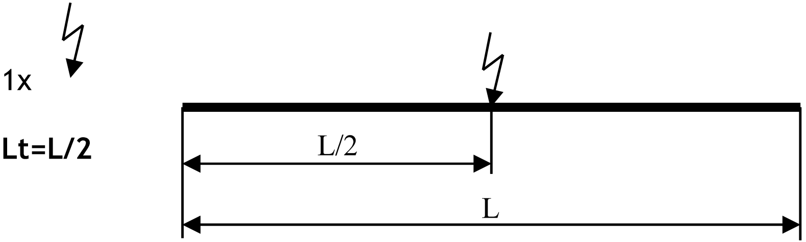
If L is the line length, Lt is the maximum length of the section to be taken into account to work out the voltage drop:
One end-line feeding point

One midway feeding point
Two feeding points
Three feeding points
Four feeding points
Five feeding points
5. QUICK SELECTION CHART
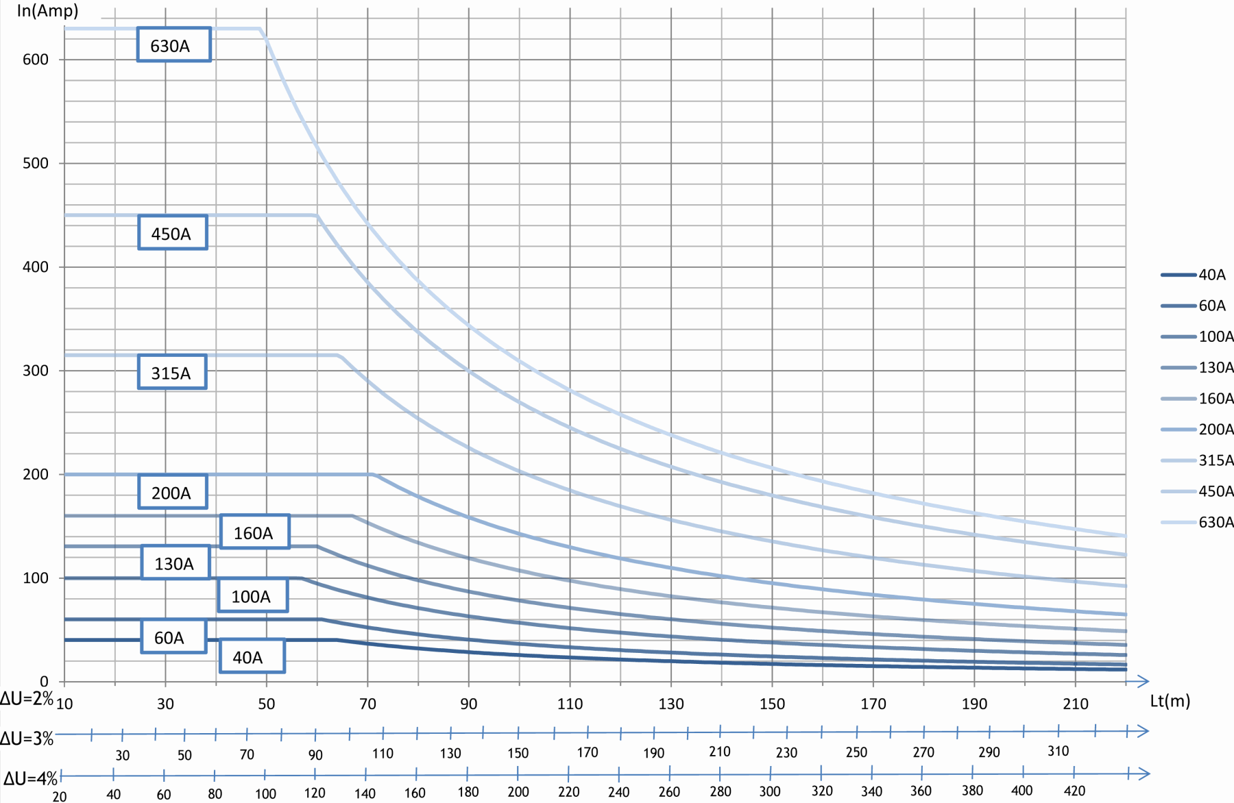
Continuous operation graph
Continuous operation under 400V at 50Hz, 35°C
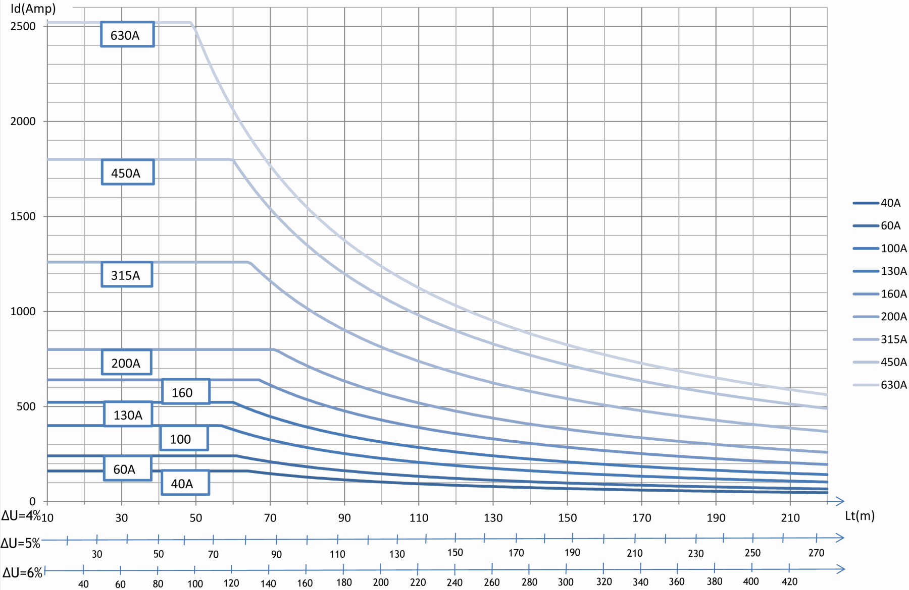
Start-up phase graph
Starting : 2 seconds maximum under 400V at 50Hz, 35°C
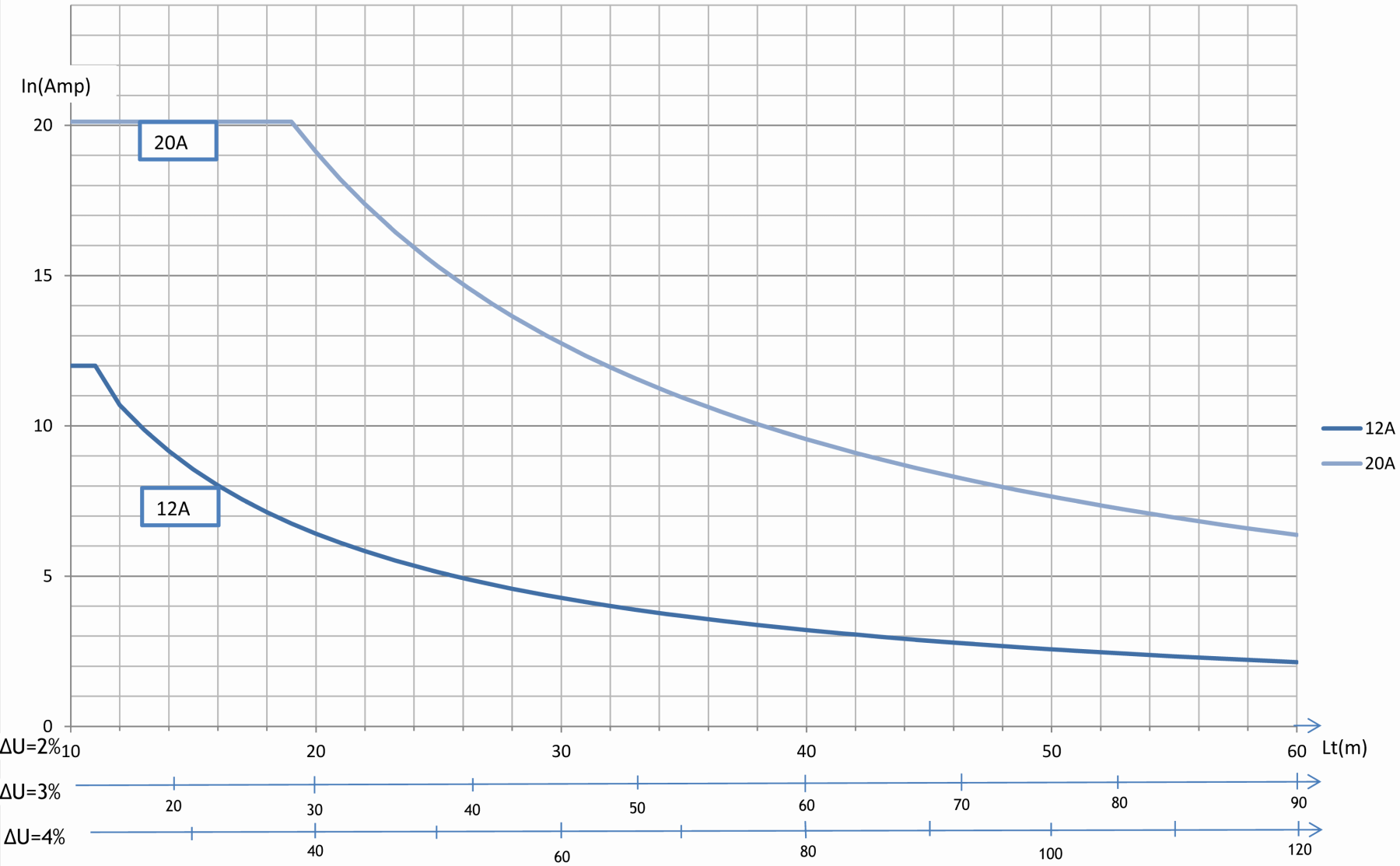
Quick Selection chart for Intensities 12A & 20A :
Continuous operation graph
Continuous operation under 400V at 50Hz, 35°C
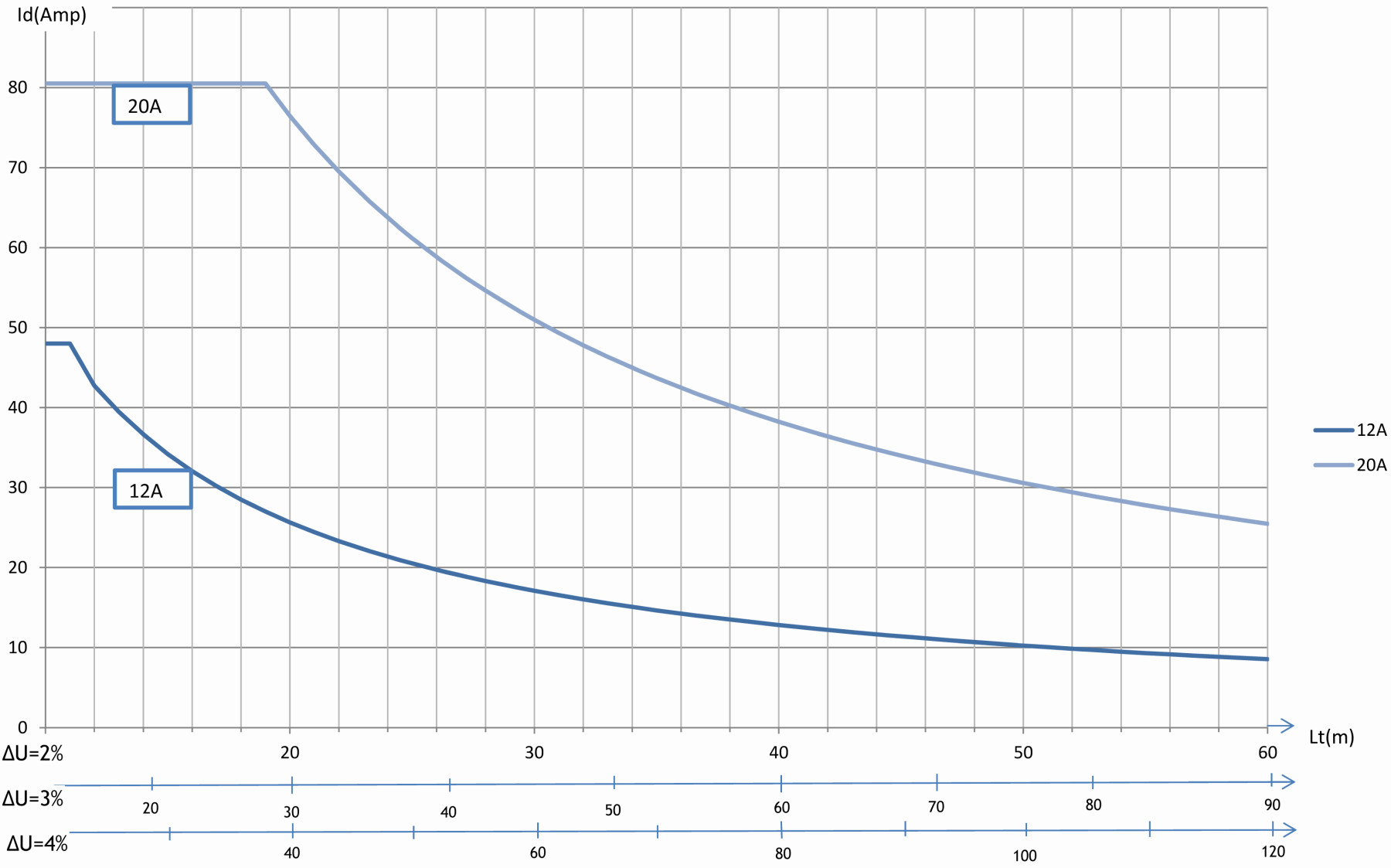
Start-up phase graph
Starting : 2 seconds maximum under 400V at 50Hz, 35°C
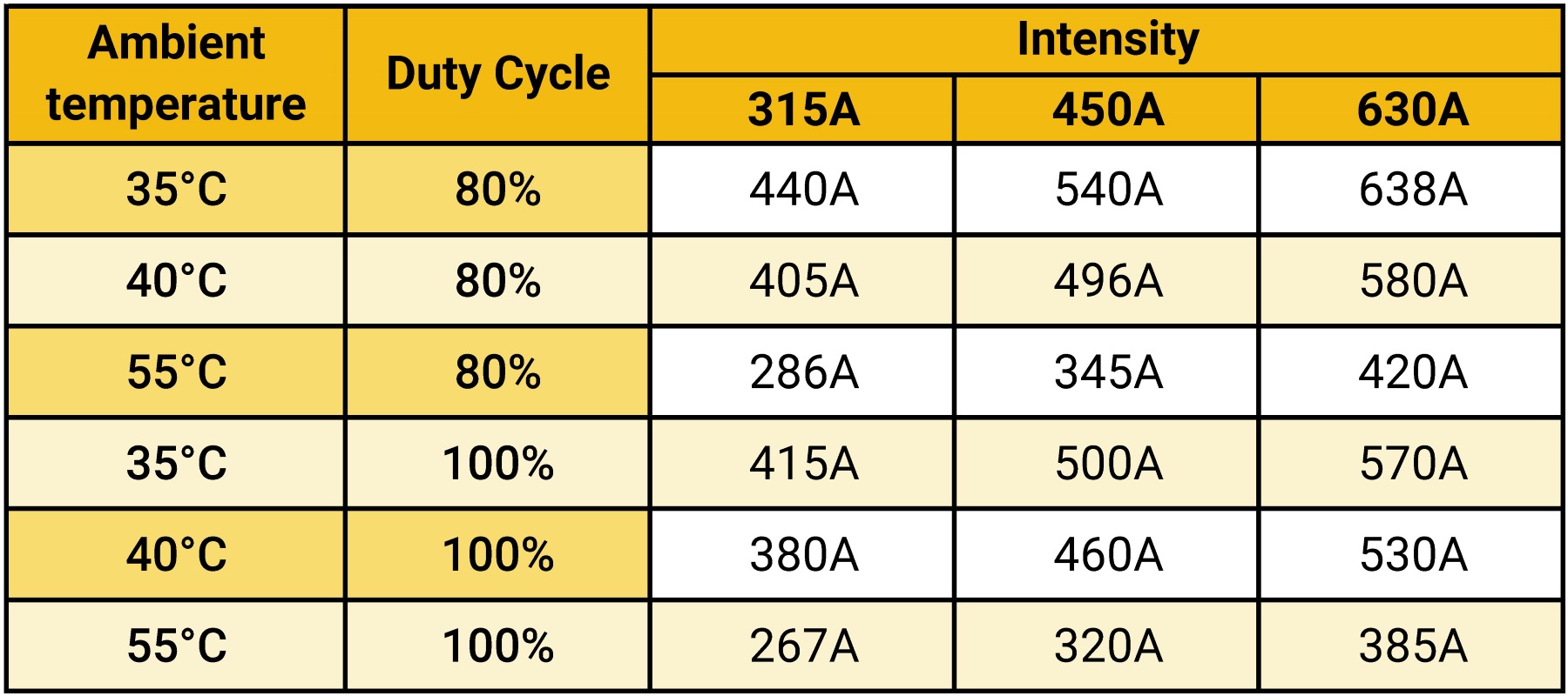
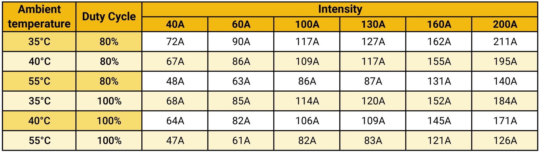
6.DUTY CYCLE FACTOR
The maximum permissible intensity in amperes depends on the maximum permissible ambient temperature for the feeding rail considered, on the ambient temperature, on the duty cycle factor (rate of equipment use over a short period), and on the Joule effect due to current carrying.
The duty cycle factor depends on the rate of equipment use, defined over ten-minute time periods and expressed in %, corresponds to the ratio running time over total time. A duty cycle factor of 80% means that the machine will be used 8 minutes per each 10-minute period.
If the calculated nominal intensity is lower or equal to the permissible intensity for a selected duty cycle factor at the maximum permissible ambient temperature, such intensity may be retained.
IN ≤ IFM
An intensity lower than the nominal current may be retained if the requirements for voltage drop upon start-up, nominal voltage drop, and duty cycle factor are met.
The higher the operating temperature, the lower the maximum permissible current.
ELITE Permissible current:
Courants admissibles MOVIT :