|
Fels.fr |
General Technical Data
 High Security and user protection
The closed profile of the IP23 rail guarantee the user against electric shock even under the rain: all the accessories ensure the IP23.
|
See related sections for special items |
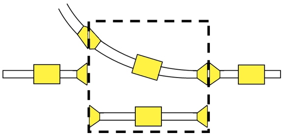
Curves |
|
|
|

1.APPLICATIONS
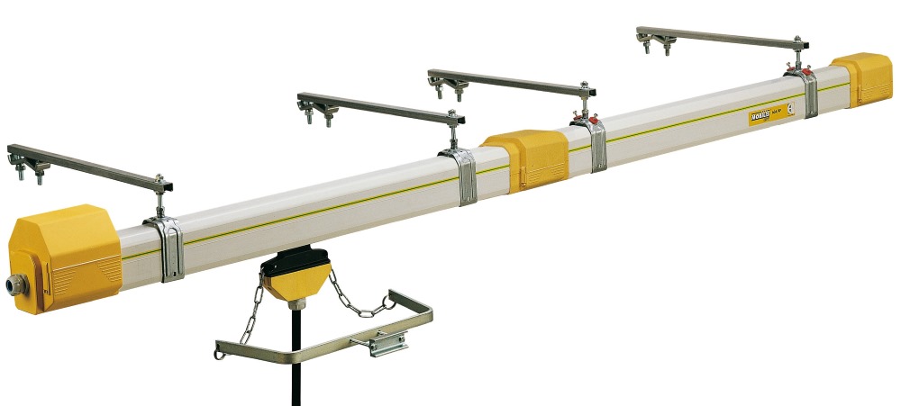
The electrical supply rails with mobile socket are generally used for the electrification of travelling cranes, cranes and hoists, narrow-aisle stores, work station equipment (tasksaver systems), elements of electric hoisting equipment, theater stages, sewage treatment and composting equipment, and other diverse applications, inside and outside.
2. GENERAL TECHNICAL DATA:
Rated operational intensity:
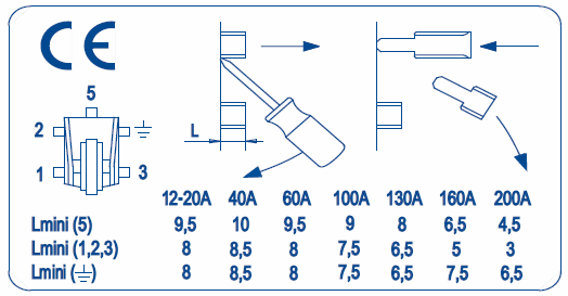
The MOBILIS ELITE lines are available in several intensities 20 A, 40 A, 60 A, 100 A, 130 A, 160 A and 200 A.
Number of poles:
The MOBILIS ELITE lines are available in 4-pole or 5-pole version.
The ground conductor (PE) is marked on the line by a green-yellow band.
The neutral conductor (N), when present, is located in the top section of the casing.
The phases (L1, L2 and L3) are located as shown on the diagram opposite.
Rated operational and insulation voltage:
750 V alternative, 50 Hz for standard version
440 V alternative, 50 Hz for high-temperature version
Temperature of use:
–30°C to +55°C in the standard version, –30°C to +75°C in the high temperature version
3. ENVIRONMENT:
Category 3 of ISO 2081 (outside mild), inside, outside use under rain or dust. A version with 600h resistance under saline mist is available. Please inquire.
Inside Outside Dust(1) With snow Low Temperatures(1) Rain
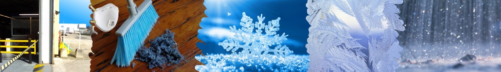
(1) With rubber gaskets for dust and special trolley for low temperatures
The Mobilis Elite feeding system is exclusively designed to run with opening of the casing facing downwards.
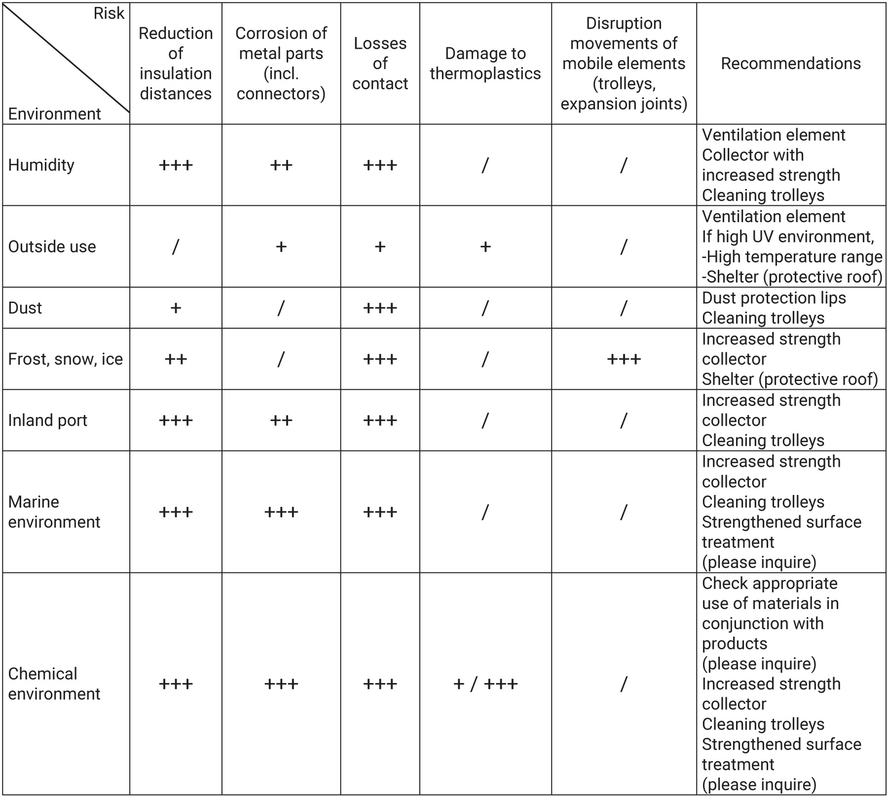
Validate suitability of the product to run in unfavorable environmental conditions (e.g. humid air flow, steam, frost…).
An unfavorable environment brings the following risks:
Legende : +++ High risks
++ Moderate risks
+ Low risks
4. APPLICABLE STANDARDS :
The Mobilis Elite range has been designed to meet Standards EN60439-2, EN60204-32 and CEI61439-6. It bears the ![]() marking.
marking.
5. PROTECTION INDEX:
A mounted line with the full set of accessories has a protection level of IP23 according to EN60529, with no gasket or with dust protection rubber gasket.
Caution: If one accessory is removed, the level of protection is eliminated.
IP2X means that the equipment is protected so that people cannot access the dangerous sections, i.e. it is impossible to introduce a standard test finger of Ø12 mm with an effort of 10 N. The equipment is also protected against solid foreign bodies, i.e. it is not possible to introduce a metal sphere of Ø12.5 mm with an effort of 30 N.
IPX3 means that the equipment is protected against rainwater falling at a maximum angle of 60° in relation to the vertical plane.
The Mobilis Elite range is designed for both inside and external use.
If a Mobilis Elite line is used in an area open to the public, additional safety measures should be installed (protection level IP4X required according to EN60204-32).
6.INSULATION DISTANCES:
The insulation distance between conductors or between conductors and accessible parts:
- Distance in the air: 10 mm min.
- Creepage distance: 30 mm min. (according to EN60204-32)
7. FLAME RESISTANCE:
All materials used to build Mobilis Elite lines are self-extinguishing; they pass successfully glowing/hot line tests under 960°C for elements in contact with live parts and V-0 according to UL-94.
8.SAFETY PINS
Line: to prevent mounting errors, 2 line elements with consecutive intensities cannot be assembled on the same line.
Identification of ground conductor: The ground conductor (PE) is marked on the line with a green-yellow band.
The connecting points on the line and the collecting trolleys are marked.
Trolley: with the safety pin system, it is not possible to insert a trolley into the line incorrectly, leading to a phase-earth connection.
9. SPACE REQUIREMENTS:
In addition to the space required for the various components (see in this section), make provision for mounting/dismounting of electrical wiring.

10.PROTECTION AGAINST FORGETTING:
Any connection, not fully established, prevents closing of covering flange, or of end-cap due to the self-breaking screws.
11. OPERATING LIFE - ENDURANCE
The lines and accessories are built to withstand several years of use in a normal industrial environment. The current collectors are designed to run for several thousand kilometers (see the Maintenance section for recommended service schedule).
12.RESISTANCE, REACTANCE, AND IMPEDANCE
UNDER NORMAL CONDITION
Impulse running:
When the rush of current is of short duration followed by long rest periods, the figures in the table below can be used.
The value of the resistance R, reactance X and impedance Z at 50 Hz at ambient temperatures of 20°C and 35°C (short period current): the figures in the table are given in mΩ/m.
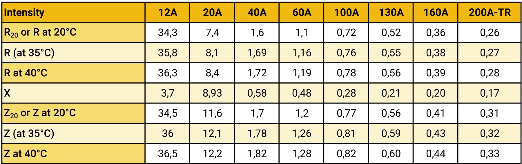
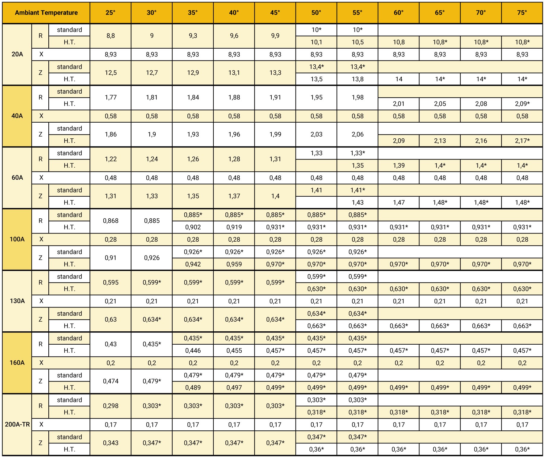
Intensive running:
The value of the resistance R, the reactance X and the impedance Z at 50 Hz according to the ambient temperature and taking into account the Joule effect for the different ratings carried by their nominal intensity and for a duty cycle as per paragraph below (* = Fm<100%).
The figures in the table should be multiplied by 10–3 to obtain Ω/m:
13. VALUE OF THE RESISTANCE R AND OF THE RESISTANCE X
OF FAULT LOOP:
See EN60439-2 and CEI61439-6, below Ddata for the application of the impedance method:
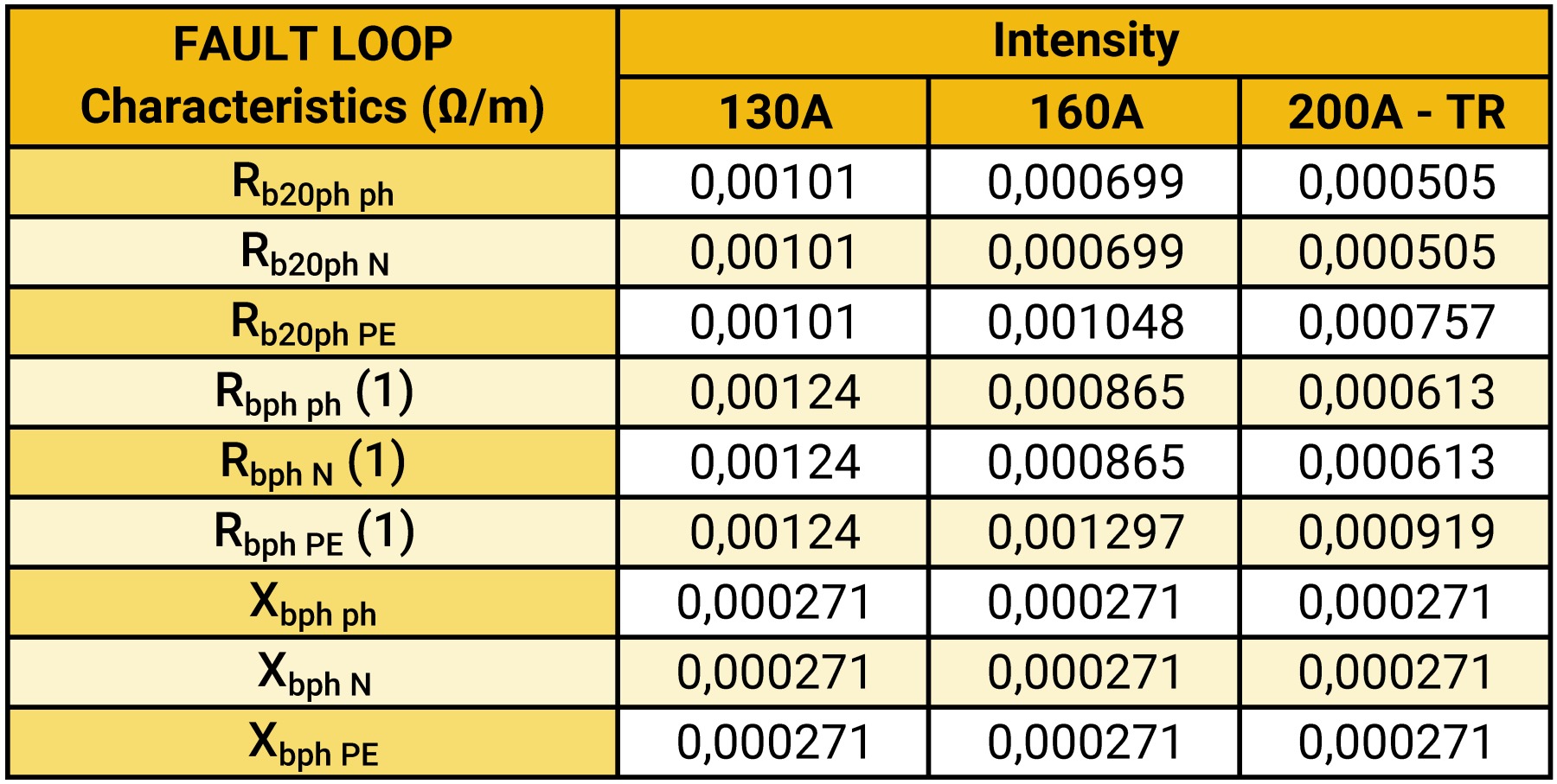
(1) at 35°C ambient temperature and maximal rated current.
Protection against short-circuits:
For intensities ≤130A, Icw<10kA.
For intensities 160A and 200A TR: Ipk=11kA
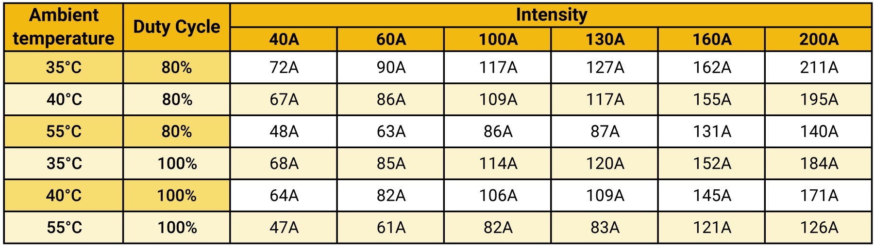
14. INTENSITY ACCORDING TO DUTY CYCLE
15. DOWNGRADING ACCORDING TO TEMPERATURE
You may use the Online calculation Tool to calculate the values according to the maximum temperature.
Or find out the maximum permissible duty cycle factor in the table below:
If, for a given intensity, Fm is higher than the value specified, it is necessary to select a higher intensity.
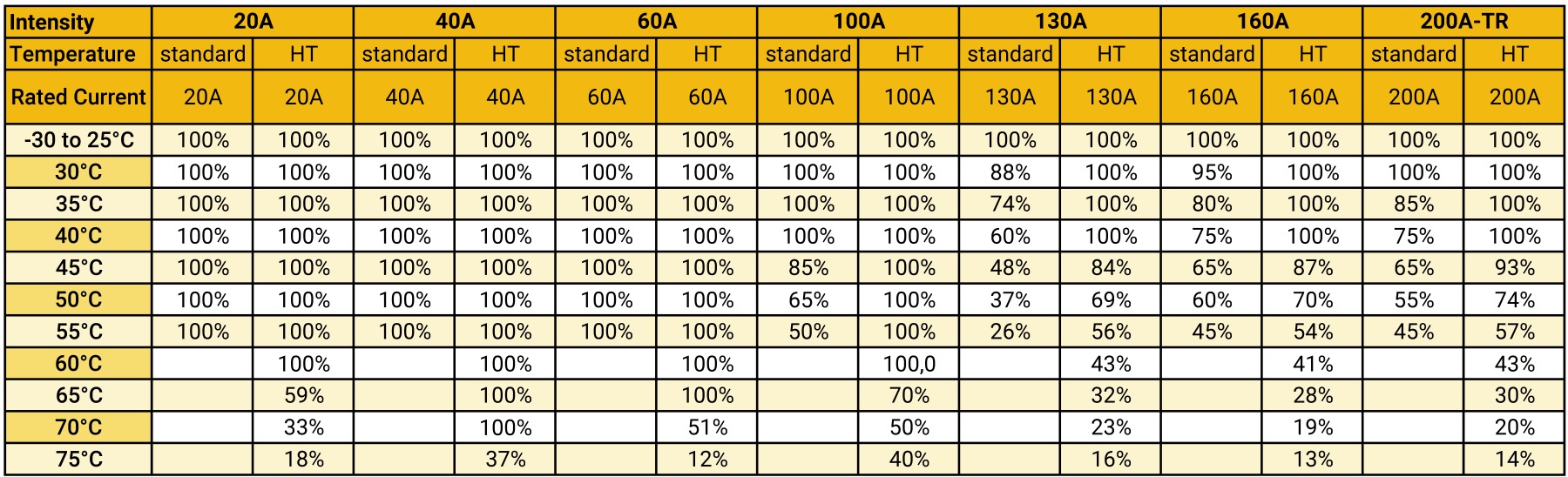
If not, refer to the following table for Elite 100% Duty Cycle Factor:
When the line carries a permanent current IN (duty cycle factor 100%), it may be necessary to downgrade the intensities according to the temperature.
If IG is the intensity of the rail and f is the correction factor defined in the table below, the new maximum permissible intensity Iadm will be:
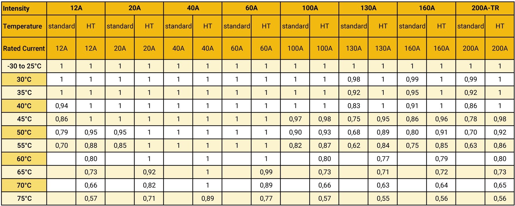
The intensity selected may be retained if the current in the line (IN) is lower than or equal to the permissible intensity (Iadm) :
IN ≤ Iadm
16. LINES CALCULATION
See Line Calculation chapter
(Data required for calculation, calculation method, charts...)
17. ONLINE CALCULATION TOOL
See the configurator
(Online calculation with intensity suggested based on data submitted)
18. COMPONENTS
See section Components
(Straight elements, trolleys, feeding boxes...)
19. ASSEMBLY INSTRUCTIONS
See related section
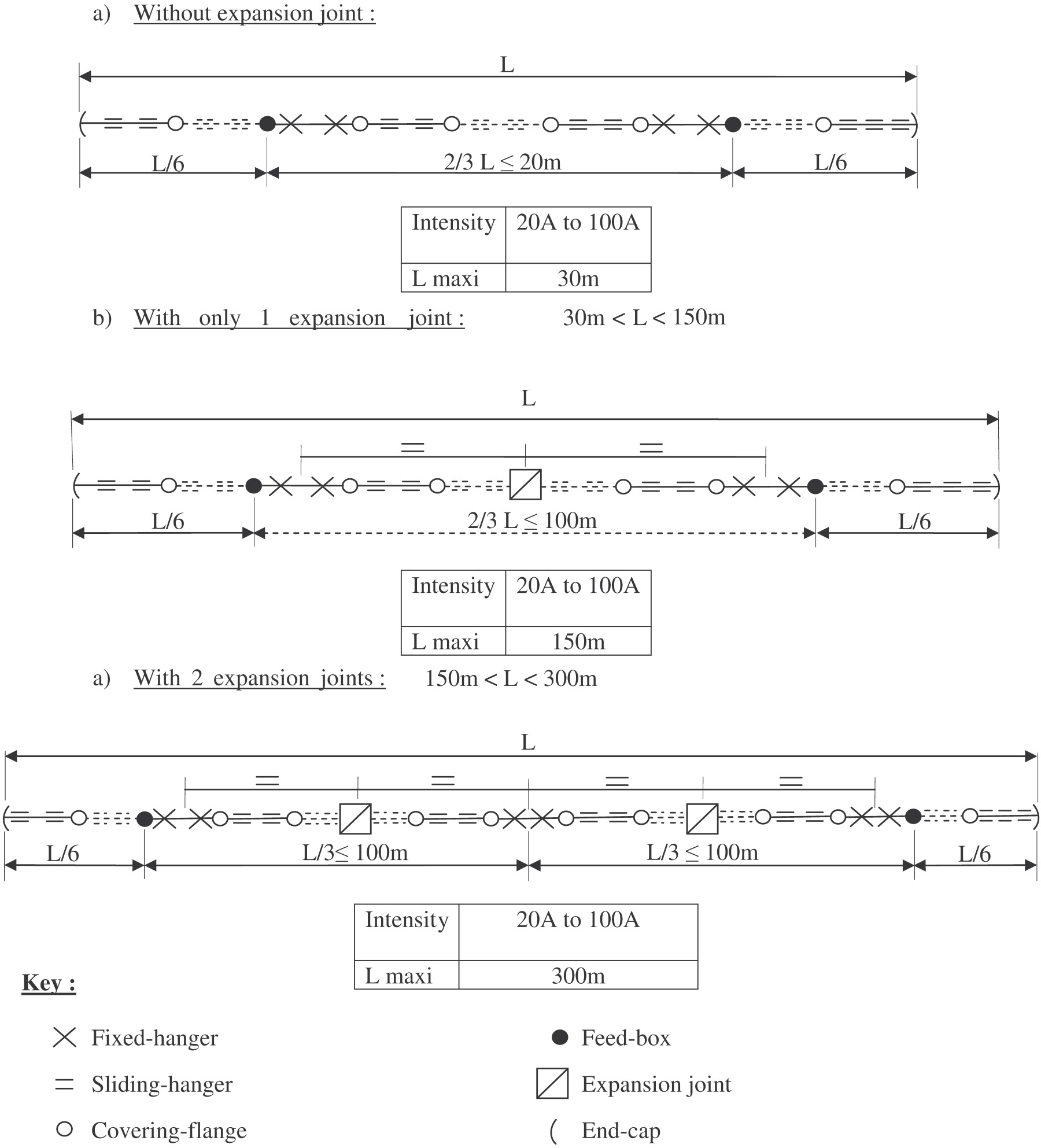
20. SPECIAL RULES FOR STRAIGHT ELEMENTS WITH RIGID WIRING
Reminder: Under normal conditions, no expansion joint is required for the installations according to the table below

However, in some cases the feeding boxes are connected with rigid cables preventing expansion, which should then be considered as anchoring points. If such is the case, the following rules shall apply.
Rules :
1.Placement of Fixed Hanger:
The anchoring points are to be located on the line element which is the closest to the connecting box.
If some highly rigid cables are used preventing expansion, the anchoring points shall be located close to line feeding:
2. End-line Feeding with rigid cable
For lines longer than the lengths in the below table, an expansion joint will be required:

For the intensity 12A, the maximal length will be determined by the voltage drop for current higher than 3,5A (for weaker currents, please consult us)
If end-line feeding uses rigid cables and an expansion joint:

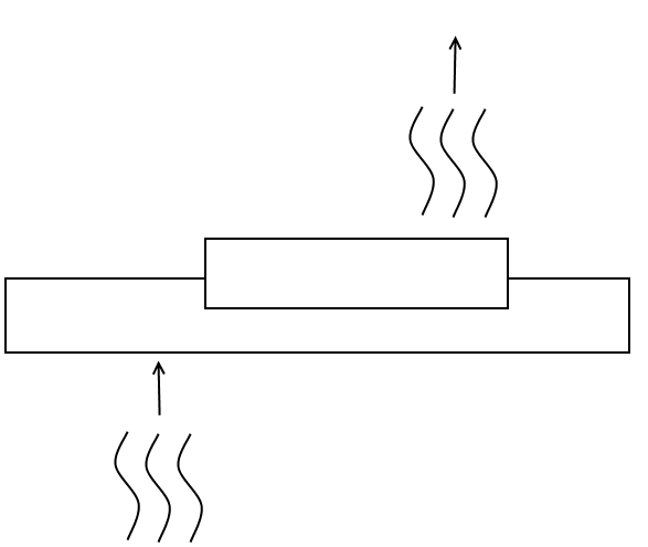
3. In-line feeding
When feeds with rigid cables are located close to the anchoring points, the standard rules apply. Otherwise, lengths without expansion joints are limited to 30m for in-line feeds between two anchoring points. Beyond this, an expansion joint is required:
21.GENERAL MAINTENANCE :
1) General points
Any intervention must be carried out with the line switched off at the mains.
Maintenance primarily concerns the conductive tracks and the trolleys.
Any damage to the conductive tracks will reduce the operating life of the brushes.
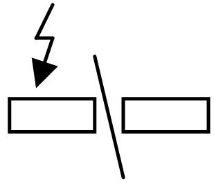
This damage may take different forms:
- Oxidation due to a chemical environment
- Abrasive dust
- Damage due to electrical arcs in the case of a faulty contact following oxidation, heavy soiling or use of worn brushes.
Regular inspection is required to check the wear of the brushes, casters of wheels and the quality of the conductive tracks according to the rate of use, the distance covered, and the chemical environment. Inspection is required when the distance covered reaches 3,000 km or after one year of use at the most.
2) Track Monitoring
The tracks normally become covered with a protective black sheen with the repeated passage of the collector trolleys with Elite. Check the surface condition of the tracks at a junction point between the casings. The surface should be smooth. If the tracks are rough to the touch, run the cleaning trolley. You will find them under the components section.
Caution : the cleaning trolley is not designed to run over long distances, its brushes wear down more rapidly than the conventional brushes.
3) Checking the brushes
Switch the line off at the mains, take out the collector.
The replacement of the brushes depends on the line intensity, since the thicker the conductor, the greater the wear reserve.
These limits are etched on the body of the ELITE trolley with 4 to 6 casters:
4) Monitoring of trolleys
Replace MOBILIS Elite trolleys every 10,000 km approximately (trolleys, 4 to 6 casters, or every 3,000 km approximately for trolleys with 2 casters – these values may be reduced according to the operating speed and the driving conditions), or in the event of excessive wear of the driving rings, chains, of the central section of the trolley casing, or of the casters. Ensure the safety pins are present when mounting.
Dust-removal of trolley sides to preserve the insulation performance.
Check particularly the following points:
- Absence of excessive play of caster axle
- Absence of excessive lateral play
- Absence of wear of guiding sides
- Free rotation of casters
5) Maintenance of circuit interruptions and transfer elements
Using insulation controller, check circuit interruption and transfer elements under voltage higher than the rated voltage.
6) Maintenance elements
Refer to the section "Spare parts" for the following items:
22.GUARANTEE
Our equipment is guaranteed one year against any material or manufacturing defect recognized by ourselves. As we are not responsible for its installation and operation, our guarantee covers only replacement or repair (at our own choosing) of the part recognized to be defective.
We do not accept responsibility for any defects arising from faulty supervision or maintenance. We also disclaim liability for any production stoppages that may result. Any arbitration shall be held in
Strasbourg, even when several defendants are involved