|
Fels.fr |
Technical Data
1.APPLICATIONS:
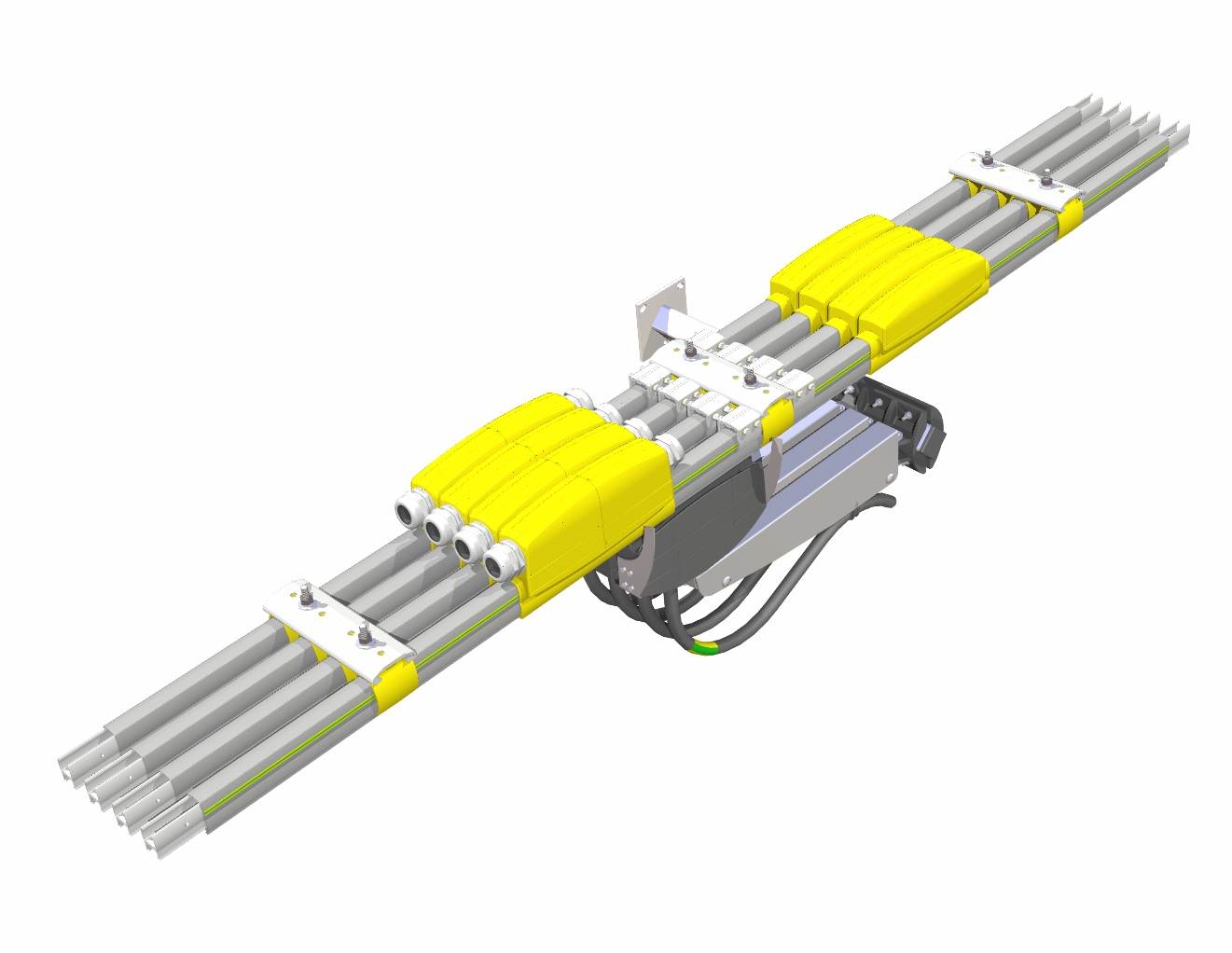
The single-conductor electrical supply rails with mobile socket are generally used for the electrification of travelling cranes, and heavy cranes and equipment, operating inside and outside.
2.GENERAL TECHNICAL DATA:
Rated intensity:
The MOVIT ELITE lines are available in several intensities 315A, 450A, and 630A
Nomber of poles :
Modular from 1 pole, the protection conductor (PE) is marked with a green-yellow stripe
Rated voltage:
750VAC at 50Hz or 60Hz
Temperature of use:
-30°C to +55°C
Protection against short-circuits:
Please inquire for intensities above Icw 8.5 kA 0.2s and Ipk 17kA
Protection against fire:
All plastic accessories used with the Mobilis Movit lines are self-extinguishing
Weight :
0,81kg/m for 315A ; 1,03kg/m for 450A ; 1,26kg/m for 630A
3.ENVIRONMENT
Inside Outside Dust With snow Low Temperature Rain

Validate suitability of the product to run in unfavorable environmental conditions (e.g. humid air flow, steam, frost…).
A version with 600h resistance under saline mist is available. Please inquire.
An unfavorable environment brings the following risks
Legend : +++ High risks
++ Moderate risks
+ Low risks

4.APPLICABLE STANDARDS:
The Mobilis Movit range has been designed to meet Standards EN60439-2, EN60204-32 and the last CEI61439-6.
It bears the ![]() marking.
marking.
5.PROTECTION INDEX:
A mounted line with the full set of accessories has a protection level of IP23 according to EN60529, with no lips and with dust protection lips.
Caution: If one accessory is removed, the level of protection is eliminated.
IP2X means that the equipment is protected so that people cannot access the dangerous sections, i.e. it is impossible to introduce a standard test finger of Ø12 mm with an effort of 10 N. The equipment is also protected against solid foreign bodies, i.e. it is not possible to introduce a metal sphere of Ø12.5 mm with an effort of 30 N.
IPX3 means that the equipment is protected against rainwater falling at a maximum angle of 60° in relation to the vertical plane.
The Mobilis Movit range is designed for both inside and external use.
If a Mobilis Movit line is used in an area open to the public, additional safety measures should be installed (protection level IP4X required according to EN60204-32).
6.INSULATION DISTANCES:
The insulation distance between conductors or between conductors and accessible parts:
- Distance in the air: 10 mm min.
- Creepage distance: 30 mm min. (according to Standard EN60204-32).
7.FLAME RESISTANCE:
All materials used to build Mobilis Movit lines are self-extinguishing; they pass successfully glowing/hot line tests under 960°C for elements in contact with live parts and V-0 according to
UL-94.
8.SAFETY PINS
Rail: The ground rail is marked on the line with a green-yellow band. The ground conductor should be installed on the outer side.
Collector: with the safety pin system, it is not possible to insert a ground collector trolley incorrectly (on phase), leading to a phase-earth connection.
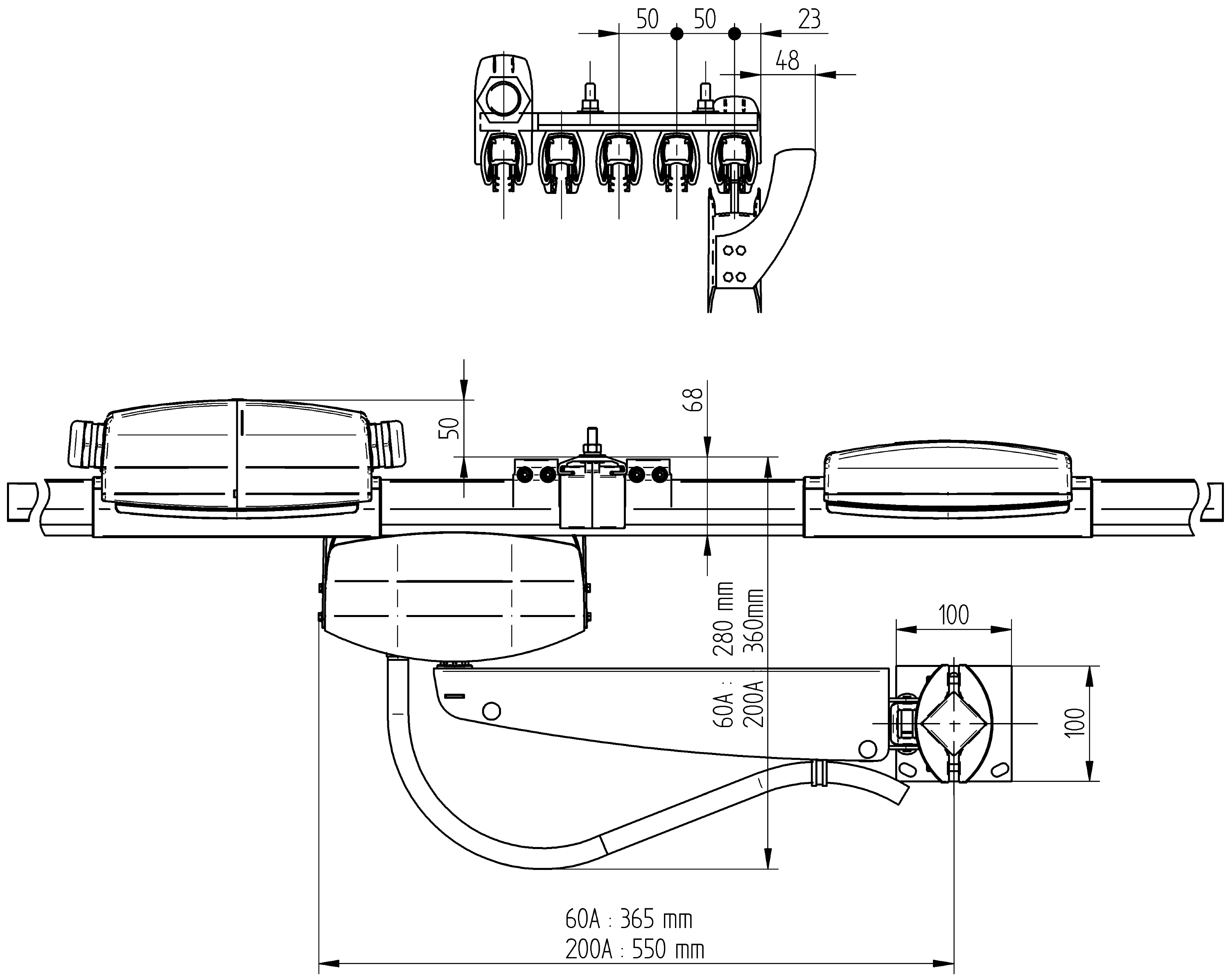
9. SPACE REQUIREMENTS:
10.LIFETIME – ENDURANCE:
The lines and accessories are built to withstand several years of use in a normal industrial environment. The current collectors are designed to run for several thousand kilometers. See the Maintenance section to know the maintenance visit frequency.
11.CALCULATION DATA:
IMPULSE RUNNING:
For determining the intensity, please refer to the data below and to the section Line calculation
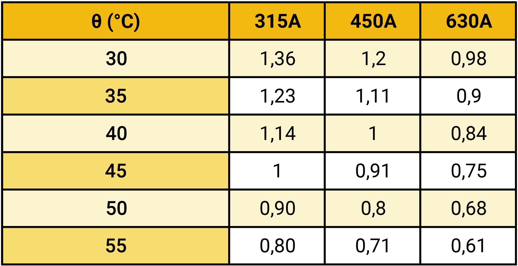
Correction factor f:
When the ambient temperature is different from 35°C, it is necessary to correct the value of the maximum permissible intensity given by the chart.
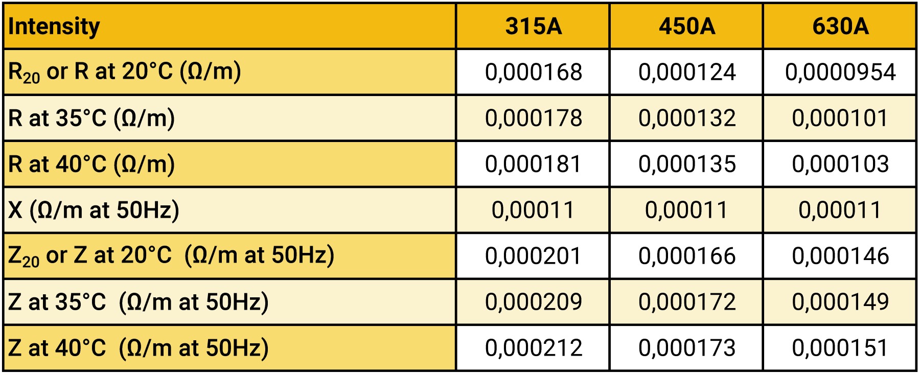
Impedance on line:
Under Fault condition:
Icw 8,5kA/0,2s
Ipk 17kA
Permissible Current according to Duty Cycle:
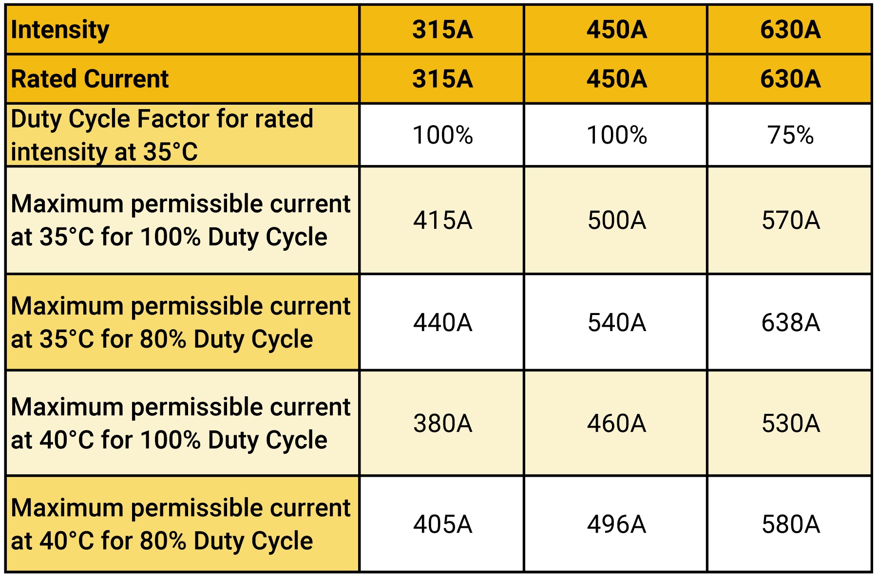
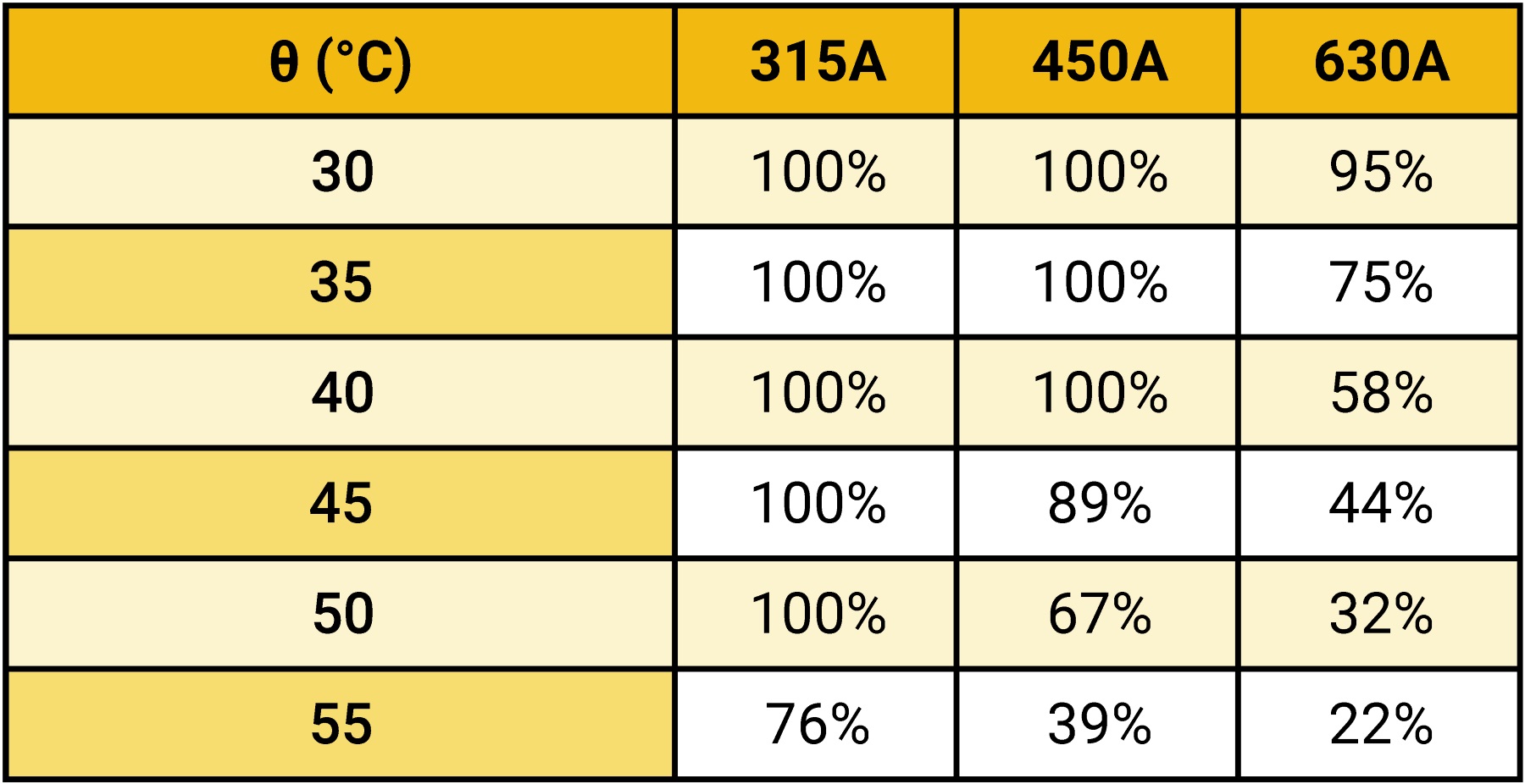
Permissible Duty Cycle Factor according to the maximum operating temperature
12.LINE CALCULATION:
See section line calculation
(Data required for calculation, calculation method, charts...)
13.ONLINE CALCULATION TOOL
See the configurator
(Online calculation with intensity suggested based on data submitted)
14.COMPONENTS
See section components
(Straight elements, trolleys, feeding boxes...)
Horizontal curves: Curvature radius<15m, please inquire
15.ASSEMBLY INSTRUCTIONS
16. GENERAL MAINTENANCE
Any intervention must be carried out with the line switched off at the mains.
Maintenance primarily concerns the brushes of the collectors and the conductive tracks of the rails.
CHECKING THE BRUSHES
The average service life of the brushes is 2,000 km.
With the line switched off, take the collector casing out of the rail.
200A Collector:
Brush replacement: the wear limit is the base of the chamfer.
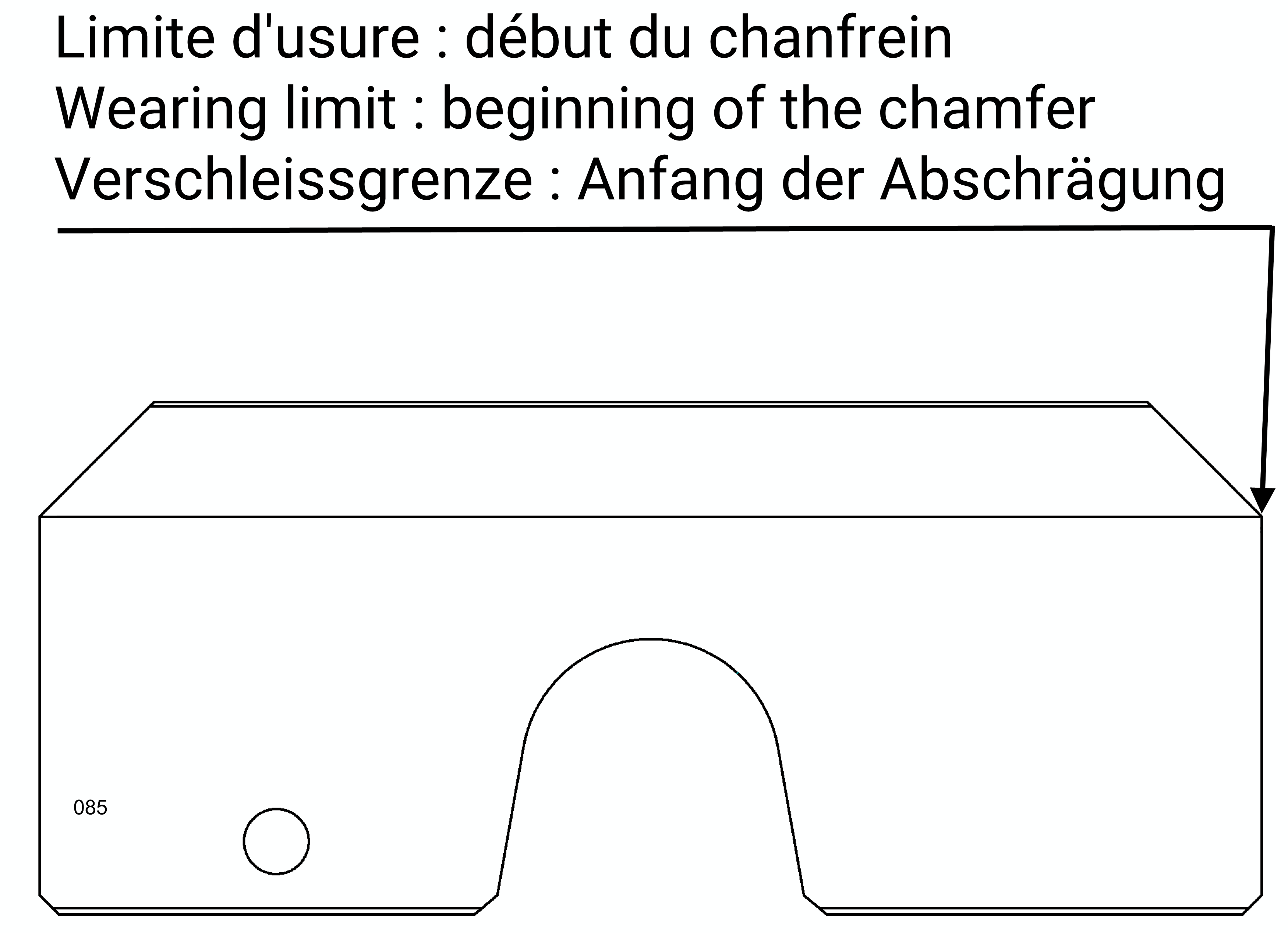
Pull up the brush to take it out of the pantograph casing, and unfasten the bolted link with the cable. Make sure the cable lug is placed correctly upon re-assembling!
60A Collector:
Brush replacement: the wear limit is the base of the chamfer.
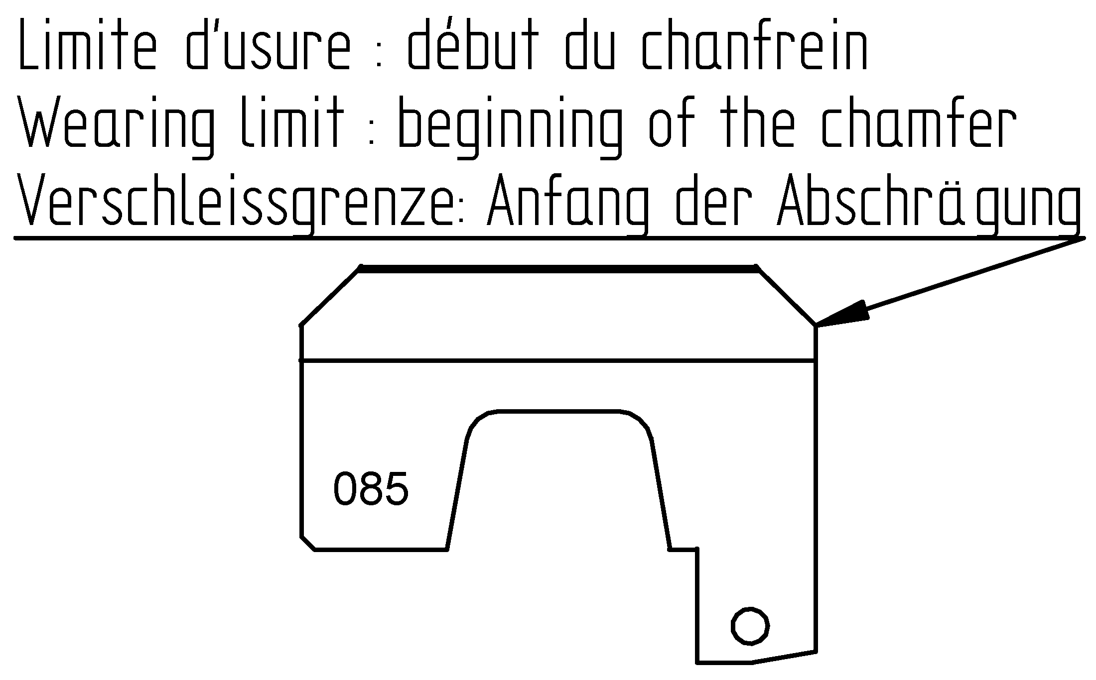
Unfasten and take out the brush fastening screw. Remove the brush and replace. Re-assemble in the reverse order.
After the brushes are fitted, make sure that the head of the collector rests smoothly in a neutral position (horizontally and in the axis).
MONITORING AND RENOVATION OF TRACKS
Track surface quality can deteriorate in different ways: under the action of dust, or with the presence of pitting (due to arcing…).
Schedule periodic maintenance (according to environment, rate of use …) to run the cleaning trolley.
Perform several passages back and forth with the cleaning brushes (abrasive foam) to remove all dust and all solid deposits, then repeat the operation with edging brushes (sanding belt, grit 120) to improve brushes quality surface.
Single collectors: facing the cleaning collector, clean the rails one by one.
Double collectors: replace a collector brush by a maintenance brush; fasten the cable to one of the maintenance collector.
Once the lines have been cleaned up, remove the cleaning collector (or put back on the collector brush in the case of double collectors), since this system is not designed to run over long distances (see section on Cleaning collector).
MONITORING OF GROUND CONTINUITY
When one (or several) expansion joints are fitted, the ground continuity on each expansion joint should be checked: once every two years
MAINTENANCE OF CIRCUIT INTERRUPTIONS
When one (or several) circuit interruptions are present, the insulation of the circuit interruption elements should be checked by means of an insulation controller, at a voltage higher than the rated voltage.
The insulation sectors should be cleaned, as necessary.
SPARE PARTS
-
Replacement Brush: 60A = MC0114 ; 200A = MC8041
-
Simple cleaning Brush : MC4190
17.GUARANTEE :
Our equipment is guaranteed one year against any material or manufacturing defect recognized by ourselves. As we are not responsible for its installation and operation, our guarantee covers only replacement or repair (at our own choosing) of the part recognized to be defective.
We do not accept responsibility for any defects arising from faulty supervision or maintenance. We also disclaim liability for any production stoppages that may result. Any arbitration shall be held in Strasbourg, even when several defendants are involved.